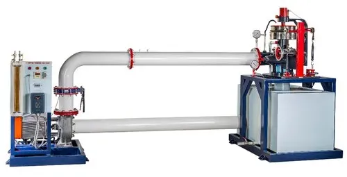
KAPLAN TURBINE TEST RIG - 1 HP
Model Number : VIPL-FPE-13
KAPLAN TURBINE TEST RIG - 1 HP
Aim: To study the characteristics of a Kaplan turbine
DESCRIPTION
The present set-up consists of a scroll casing housing a runner. Water enters the turbine through the Stationary guide vanes and passes through the runner axially. The runner has a hub and vanes, Which are mounted on it. The water is fed to the turbine by means of Centrifugal Pump. The runner is directly mounted on one end of a central SS shaft and other end is connected to a brake arrangement. A transparent hollow cylinder made of acrylic is fitted in between the draft tube and the Casing for observation of flow. Load is applied to the turbine with the help of belt brake arrangement. So that the efficiency of the turbine can be calculated. The set-up is supplied with control panel. A draft tube is fitted on the outlet of the turbine. The set-up is complete with guide mechanism. Pressure and Vacuum gauges are fitted at the inlet and outlet of the turbine to measure the total supply head on the turbine.
EXPERIMENTS:
- To study the operation of Kaplan turbine.
- To determine the Output Power of Kaplan Turbine.
- To determine the turbine efficiency.
UTILITIES:
- Water Supply & Drain.
- Electricity 20 kw, 440V AC, Three Phase.
- Floor Area 1.5m x 0.75 m.
- Tachometer to find out RPM
| Output Power | 1 HP |
|---|---|
| Discharge | 1200 LPM |
| Supply Head | 10-15 m |
| Runner | with Curved Vanes |
| Dynamometer | Rope Brake type, Dia 200mm |
| Sump Tank | Capacity 200 Liters |
| Water Circulation | Centrifugal Pump, Capacity 5 HP, Three Phase |
| Discharge Measurement | Venturi meter with pressure gauges |
| Rope Brake Dynamometer | |
| Control panel comprises of | Standard make Starter, Mains Indicator Tanks will be made of Stainless Steel. |
| Set Up | The whole set-up is well designed and arranged in a good quality painted structure. |