

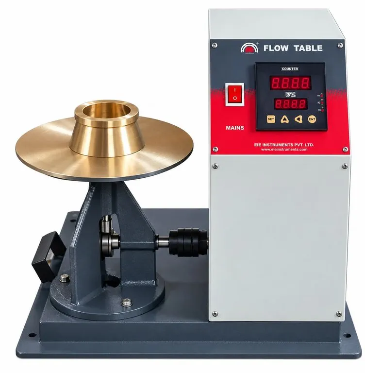
FLOW TABLE - CEMENT - EN 1015-3, EN 13395-1, EN 459 - MOTORISED MODEL
Model Number : EIE-FTCM30
FLOW TABLE VARIETY (FOR CEMENT)
- FOR BUILDING LIMES - HAND OPERATED - 30CM DIA - AS PER IS 6932
- HAND OPERATED - 25CM DIA - GUNMETAL TOP - IS 5512
- HAND OPERATED - 25CM DIA - STEEL TOP - IS 5512
- HAND OPERATED - GUNMETAL TOP - (ASTM C230)
- MOTORISED - (ASTM C230)
- MOTORISED - 25CM DIA - GUNMETAL TOP - IS 5512
- MOTORISED - 25CM DIA - M.S. TOP - IS 5512
- MOTORISED - 30CM DIA - AS PER EN 1015-3
Compliance with following International Standards :
EN 1015-3, EN 13395-1, and EN 459-2
Application :
Used to determine the consistency of mortars and building lime.
Brief construction description :
The flow table apparatus consists of an integrally cast rigid iron frame and a circular rigid table top [300 ± 1 mm] in diameter, with a shaft attached perpendicular to the table top by means of a screw thread. The table top and shaft with contact shoulder will be mounted on a frame in such a manner that it can be raised and dropped vertically through the specified height of 10 ± 0.2 mm by means of a rotated cam.
The table top will have a fine machined plane surface, free of blowholes and surface defects. The table top will be of bronze, having a Rockwell hardness number not less that HRB 25 with an edge thickness of 7.5 mm, and will have six integral radial stiffening ribs.
The table top and attached shaft weighs must be between 4.20 kg and 4.50 kg and the weight will be symmetrical around the center of the shaft.
Cam & Shaft :
The cam and vertical shaft will be of medium carbon machinery steel, hardened on the end of the shaft contacting the cam and the tip of the cam contacting the shaft. The shaft will be straight and the difference between the diameter of the shaft and the diameter of the bore of the frame will be not less than 0.002 in [0.05 mm]. The end of the shaft will not fall upon the cam at the end of the drop, but will make contact with the cam not less than 120° from the point of drop.
The face of the cam will be a smooth spiraled curve of uniformly increasing radius from 1.2-11.4 in [13 - 32mm] in 360° and there will be no appreciable jar as the shaft comes into contact with the cam. The cam will be so located and the contact faces of the cam and shaft will be such that the table does not rotate more than one revolution in 25 drops. The surfaces of the frame and of the table that come into contact at the end of the drop will be maintained smooth, plane, and horizontal and parallel with the upper surface of the table and will make continuous contact over a full 360°.
Flow Mould :
The conical mold for casting the flow specimen will be made of cast bronze or brass. The Rockwell hardness number of the metal will be not less than 25 HRB. The height of the mold will be [60.0 ± 0.5 mm]. The diameter of the top opening will be [70.0 ± 0.5 mm]. The diameter of the bottom opening will be [100.0 ± 0.5 mm]. The surfaces of the base and top will be parallel and at right angles to the vertical axis of the cone. The mold will have a minimum wall thickness of [2 mm].
Supporting Frame :
The supporting frame of the flow table will be integrally cast of fine-grained, high-grade cast iron. The frame casting will have three integral stiffening ribs extending the full height of the frame and located 120° apart. The top of the frame will be chilled to a depth of approximately 1.4 in [6 mm], and the face will be ground and lapped square with the bore to give 360° contact with the shaft shoulder. The underside of the base of the frame will be ground to secure a complete contact with the steel plate beneath.
Motorized Mechanism :
The flow table will be driven by a motor connected to the cam shaft through an enclosed worm gear speed reducer and flexible coupling. The speed of the cam shaft will be approximately 60 rev/min. The motor drive mechanism will not be fastened or mounted on the table base plate or frame. Suitable for operation on 230 Volts 50 cycles. Single Phase, A.C. Supply. Complete with spring loaded tamper.
Following accessories will be the part of standard supply.
- Flow table mould Specifications as per EN : 1 No
- Digital Counter, Range : 0-999 rev/min : 1 No
Following accessories will be at extra cost.
- Vernier Caliper 300 mm capacity
- Steel tamper
Determination of consistence of fresh mortar (by flow table) : BS EN 1015-3
The flow value is determined by measuring the mean diameter of a test sample. The bulk sample of fresh mortar is reduced to a minimum sample size of 1.5 litres. Where it is desired to measure the flow of dry mortars these should be mixed with water in accordance with the requirements of BS EN 1015-2. Mortar Testing Page 7 of 20 Final Version Learning Text Mortar testing The test procedure involves placing the mould (60 mm in height, internal diameter: base 100 mm - top 70 mm) in the center of the flow table and filling it in two layers each layer being tamped ten times with the tamper. It is important that the mould is held firmly in place during this operation. The excess mortar is removed from the top of the mould with the palette knife and the area around the base of the mould cleaned with a cloth. A period of approximately 15 seconds is allowed to elapse and the mould is then removed, the table is jolted 15 times at a rate of one jolt per second. The diameter of the spread mortar is measured in two directions at right angles to each other using calipers, both results are reported.